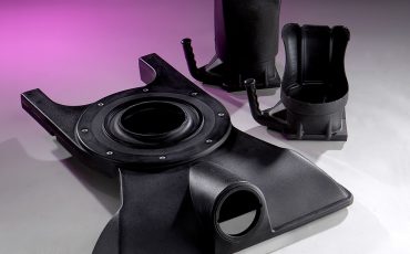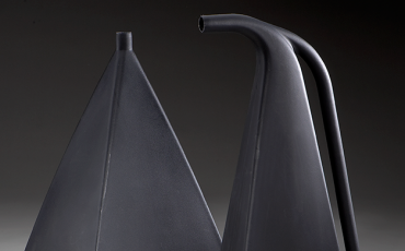

Are you designing a part for rotational molding? Then remember to consider corner angle limits. They directly affect part quality, moldability, and long-term performance. It’s also important to understand how plastic flows, melts, and accumulates inside a rotational mold. By following some best practices, you can design plastic parts for consistent, repeatable production.
Why Corner Angles Matter
During rotational molding, plastic powder moves throughout the mold before melting and fusing into a uniform wall. Tight corners restrict this movement and can lead to part defects. If angles become too acute (i.e., more than 0° and less than 90°), powder can bridge and leave voids or thin sections that compromise part strength and appearance.
Recommended Corner Angle Limits
According to the Association of Rotational Molders (ARM), corner angles that are less than ARM’s recommended limits may fail to fill completely, resulting in part rejects and higher production costs. ARM’s design guidelines provide the following thresholds:
- ≥ 90°: Molds easily with most rotomolding materials
- 45°: Achievable with standard polyethylene powders
- 30°: Minimum recommended angle for polyethylene
Angles less than 30° significantly increase the risk of bridging, trapped air, and incomplete filling.
The Role of Corner Radii
Corner angle limits work hand‑in‑hand with corner radii, another consideration in rotational molding design. ARM recommends generous radiusing to reduce stress concentrations and improve flow. Optimal radii are approximately 75% of the nominal wall thickness. Inside radii that are less than 25% of wall thickness increase stress and reduce moldability.
Sharp inside corners heat more slowly and fill last, making them prime locations for defects. By contrast, outside corners tend to accumulate extra material.
Material and Processing Considerations
Polyethylene is the most common rotational molding material, but it’s not the only plastic that’s used. For dry powders, improving dry flow characteristics can help fill tight corners. ARM notes that coarser powders or micropellets with particle sizes roughly 50% larger than standard powder can reduce bridging in difficult geometries.
Adding a small vent hole of approximately 1/16” at the tip of a sharp corner also helps. This allows trapped air to escape during heating. It also improves filling and reduces void formation. Note that there are differences between blind holes, through holes, and undercut holes, all of which are used to equalize the pressure on the part’s inner and outer walls during mold heating and cooling.
Ask Gregstrom for Rotomolding Design Assistance
Whenever possible, remove sharp corners from your rotational molding part design. Use smooth transitions, adequate radii, and angles greater than 45° to improve part consistency. Remember that rotomolded parts behave like hollow shells, and that their geometry must support free movement and balanced heating.
Part designers who follow these guidelines and work with Gregstrom Corporation can enjoy stronger, more reliable parts and fewer molding challenges. Proper corner design improves manufacturability, enhances structural performance, reduces scrap, and supports long-term durability in demanding applications. If you’re ready to get started, we’re ready to help.
Contact Gregstrom for rotational molding services that deliver greater value.