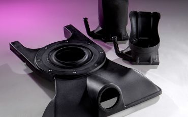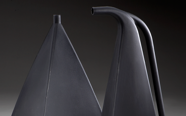
Heavy gauge thermoforming turns thick plastic sheets into extremely durable parts. Applications include enclosures, housings, and panels for vehicles, instruments, and equipment. For best results, part designers need to account for tool selection, dimensioning, and stretch or draw ratio. These aren’t the only design considerations for heavy gauge thermoforming, but they’re a good place to start.
Tool Selection
Heavy gauge thermoforming uses production tooling that’s cast or machined. These tools have comparable lead times and support part details. The size and complexity of the thermoformed part usually determines the type of tool that’s used. Typically, cast or machined molds are temperature-controlled. With machined molds, cooling plates are required only for tools that lack internal plumbing.
Prototyping can be done with tools made of epoxy, wood, or other materials; however, these molds are neither temperature-controlled nor good conductors of heat. Therefore, these lower-cost molds are only good for short runs where part dimensions are not highly critical.
Dimensioning
Heavy gauge thermoforming is a single-sided process that controls only the mold side of a part. During part dimensioning then, designers need to measure from the tool’s surface. Thermoformed parts that use male molds are dimensioned to the inside of the part. Parts that use female molds are dimensioned to the outside of the part instead.
Stretch or Draw Ratio
Stretch or draw ratio describes the relationship between the surface area of a formed part to the starting area of the original plastic sheet. The larger number represents the beginning surface area of the unformed plastic sheet at the opening of the mold. The smaller number represents the size of the part once the plastic is formed over the mold’s interior surface.
Heavy gauge thermoforming can support stretch or draw ratios that are higher than 3:1 (especially with male tooling), but part designers need to understand that thinning will occur. To calculate the stretch ratio, the average length, width, and depth of a part are considered. For a 3:1 draw that starts with a .250” sheet, the estimated average finished wall thickness is .080”.
More Design Considerations
Tool selection, dimensioning, stretch ratio, and draw ratio aren’t the only design considerations for heavy gauge thermoforming. Part designers also need to consider tolerances, radii, ribs, undercuts draft, defects, material selection, and parts finishing. Picking the right manufacturing partner is an important decision, too.
Heavy Gauge Thermoforming from Gregstrom
Gregstorm Corporation of Woburn, Massachusetts (USA) is a heavy gauge thermoformer that provides design assistance and supports larger sheet sizes than most of our regional competitors can handle. To learn more about us and how we can help you, contact us.