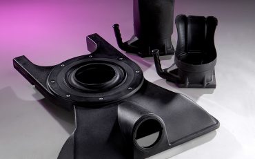
Rotational molding offers design engineers geometric freedom, low tooling costs, and the ability to produce large, stress‑free, hollow structures. Rotomolding, as this plastics process is also known, isn’t free from design and manufacturing constraints, however. Therefore, it’s important to start your project with some basics in mind.
This article by Gregstrom, a Made in USA rotomolder with 75+ years of experience, provides some tips for design engineers. Contact us to discuss your specific rotomolding application. In addition to rotational molding, we offer tooling services, design reviews, help with material selection, parts finishing, and testing and assembly.
Wall Thickness and Reinforcements
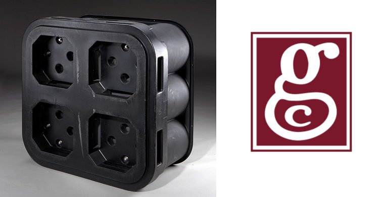
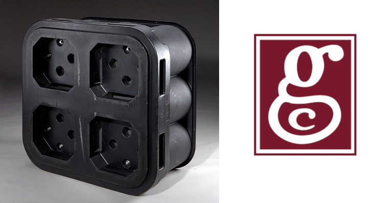
Wall thickness in rotomolding is controlled by material charge and heating time. Therefore, design rotomolded parts for nominally uniform walls and avoid sudden transitions. Thick sections accumulate heat and cool slowly, increasing cycle time and internal stress. Thin sections may fail to fully fuse. For part reinforcement, use ribs, contours, or kiss‑offs rather than localized thickening.
Corners, Radii, and Transitions
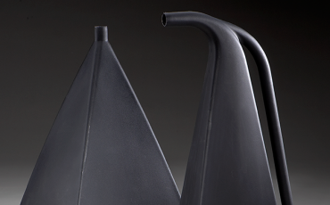
Sharp corners are a common failure point with rotomolded parts. That’s because they trap heat, create thin inside corners, and concentrate stresses. Apply inside radii that are at least equal to your nominal wall thickness. Apply outside radii as large as your design allows. In addition, use smooth transitions to improve resin flow and reduce void formation.
Draft Angles and Part Release
Because rotomolded parts shrink away from the mold during cooling, the draft requirements are more forgiving than with injection molding. In fact, simple cylindrical or open shapes may require little or no draft. However, textured surfaces, deep features, or male molds require 3–5 degrees of draft to ensure clean release and avoid part distortion during demolding.
Flat Surfaces and Warpage with Rotomolded Parts
Flat walls are inherently unstable because of thermal contraction and the absence of internal support during rotomolding. To maintain dimensional stability, use these approaches:
- Add crowns or compound curvature
- Use ribs or kiss‑offs to stiffen large spans
- Set realistic flatness tolerances early in the design process
These strategies reduce creep, improve dimensional stability, and minimize cosmetic defects.
Designing for Cost and Manufacturability
Rotational molding’s low tooling costs are one of its main advantages over injection molding. Still, it’s important to remember that part features that require complex mold splits, deep undercuts, or active inserts can increase tooling costs and mold maintenance. By working closely with a rotational molder, design engineers can optimize mold piece count along with cycle times.
Ask Gregstrom for Rotomolded Parts
Gregstrom Corporation of Bedford, New Hampshire (USA) is the rotomolder that does more. In addition to rotational molding, we offer tooling services, part design assistance, and help with material selection. From prototyping to production, Gregstrom is ready to help you succeed. Contact us to request a quote or discussion your application.